


How to Use Orca Slicer
Orca Slicer takes a 3D model and turns it into instructions your printer can follow. You load a file, tell it which printer and filament you are using, decide how the object should be built, and it produces a G-code file that drives the machine.
That is the whole job. Everything below is a task you might need along the way.
This page is built to be dipped into, not read end to end. Find the thing you are trying to do, do it, and get back to printing. Each screenshot here comes from a real OrcaSlicer window, so what you see on the page is what you will see on your screen.
Getting started with Orca Slicer
Install Orca Slicer on Windows, macOS or Linux
Download the build for your operating system, then run it. There is no licence key, no account and no trial period. It is free and open source.
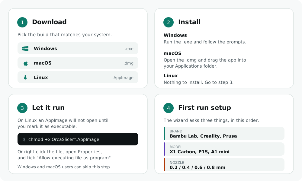
Windows. Run the installer and follow the prompts. There is also a Microsoft Store listing if you would rather install it that way, which handles updates for you.
macOS. Open the disk image and drag OrcaSlicer into your Applications folder. The first time you open it, macOS may warn you that the app is from an unidentified developer. Right click the app and choose Open, and the warning gives you an option to continue.
Linux. The AppImage is the simplest route. Download it, mark it executable, and run it. Nothing gets installed system wide. OrcaSlicer is also on Flathub, which is the better choice if you want your package manager to handle updates.
If the program installs but will not open, or opens and immediately closes, that is almost always a graphics driver problem rather than a bad download. The troubleshooting page covers the specific causes.
What you see when the program opens
The window splits into three parts, and once you know what each one does the rest of the program stops feeling crowded.

The left panel is your setup. The top block is your printer, the nozzle it is fitted with, and the build plate you are using. Below that is your filament. Below that is the process, which is the long list of print settings grouped into tabs called Quality, Strength, Speed, Support, Multimaterial and Others.
The middle is the build plate, where your model sits. The row of icons across the top is the toolbar, and every model editing tool lives there.
The top strip holds the Prepare, Preview, Device, Project and Calibration tabs. You will spend most of your time in Prepare, then switch to Preview after slicing to check the result.
The two buttons at the top right slice the plate and then send or export the result. What the second button says depends on your printer, which is covered further down.
Switch between Simple, Advanced and Expert mode
OrcaSlicer hides settings on purpose. There are four modes, and each one shows more of the program than the last.
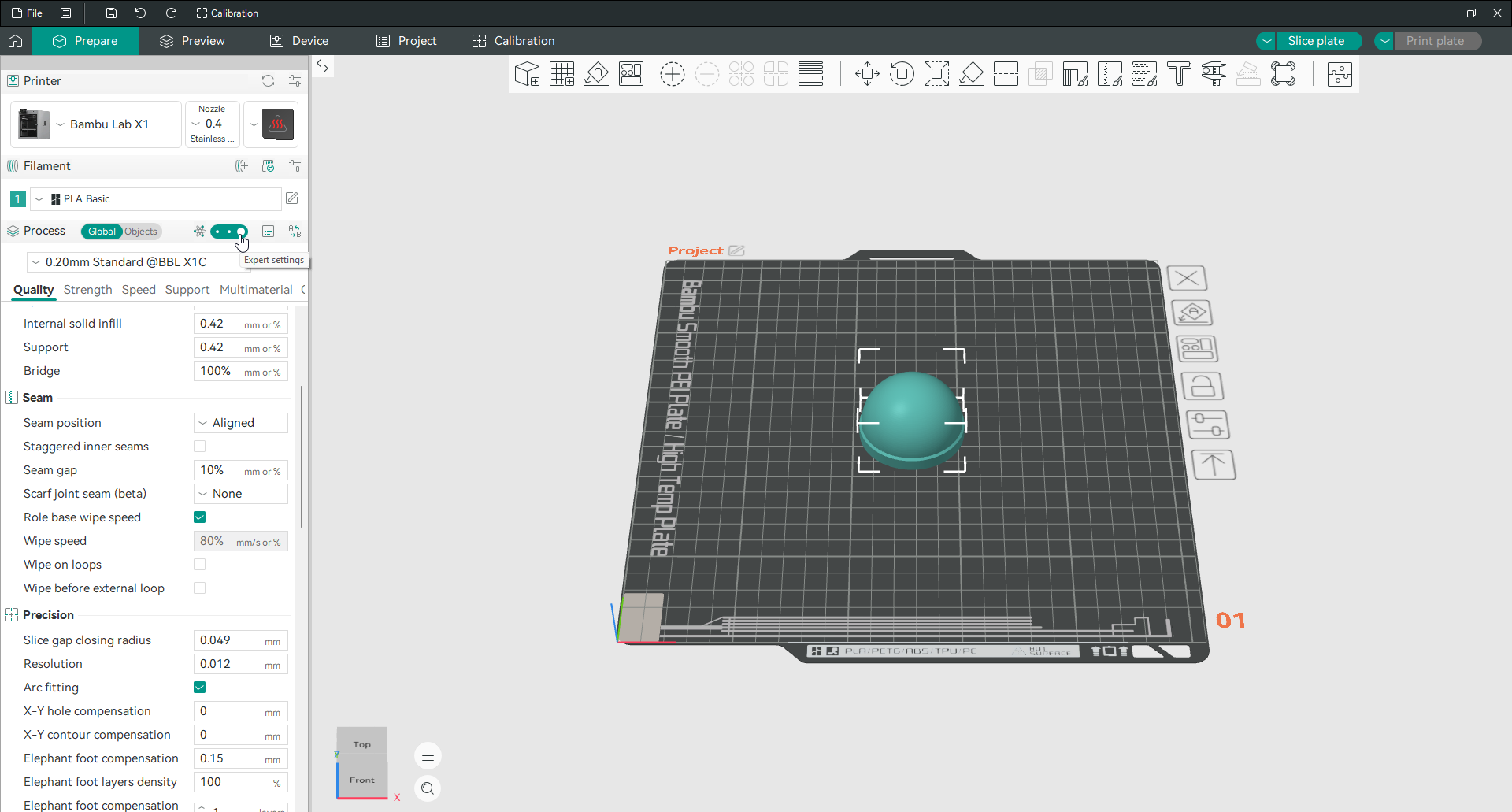
This is worth understanding early, because it explains a problem people hit constantly. You read about a setting, you go looking for it, and it is not there. Nine times out of ten the setting exists and your mode is too low to see it.
Simple mode shows the handful of settings most people change. Advanced adds the rest of the everyday controls. Expert adds the fine detail, including things like Z contouring and the Arachne wall generator parameters. Developer mode is for people working on the slicer itself.
If you are following a guide and cannot find what it describes, switch to Advanced or Expert before you assume the setting was removed.
Change the language, units or turn on dark mode
All three live in the same place. Click the menu icon next to File, choose Preferences, and stay on the General tab.
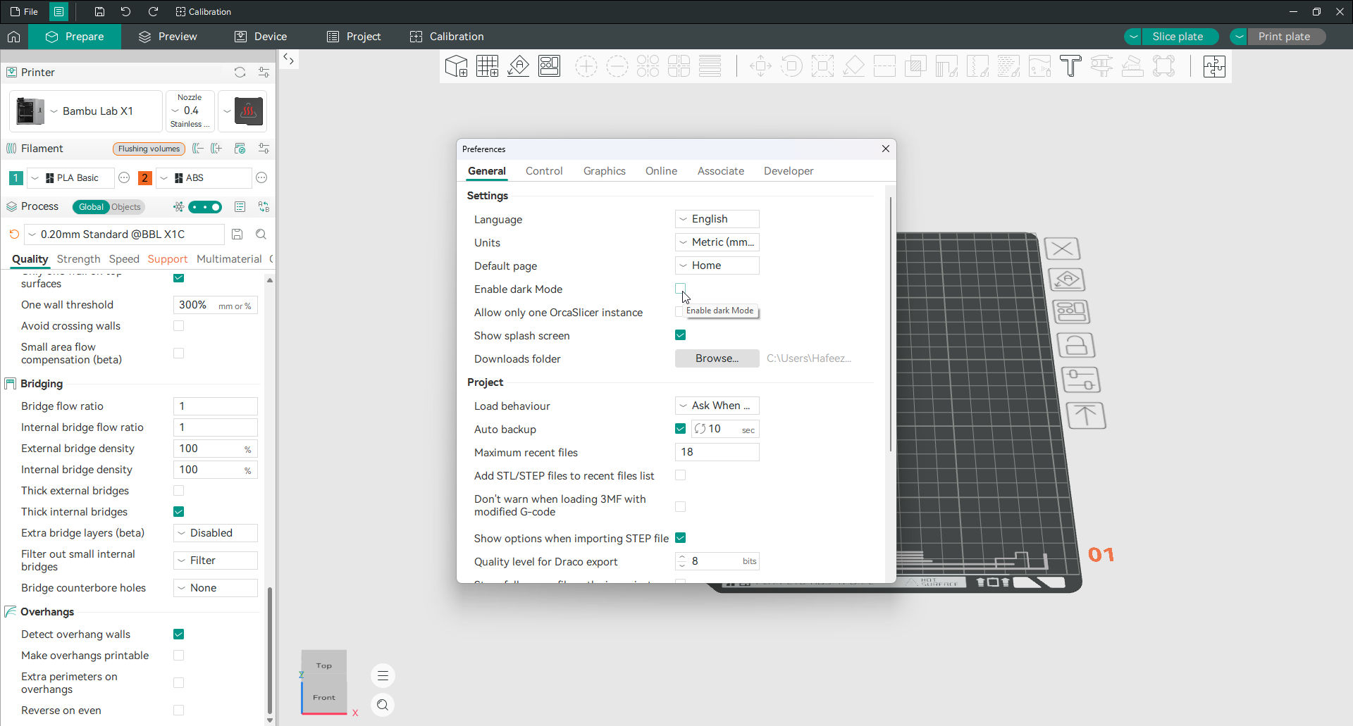
Language changes the whole interface. Units switches between metric and imperial. Enable dark Mode is a checkbox and is off by default, so if you were looking for a dark theme, that is where it is.
The same tab holds a few other things worth knowing about. Auto backup is on and saves your work every ten seconds. Load behaviour decides what happens when you open a project file that carries its own settings, and by default it asks you each time. The Downloads folder is where models pulled in from online libraries land.
Adding and connecting your printer
Add a printer
OrcaSlicer thinks about printers in three steps: the brand, then the model, then the nozzle fitted to it. You need all three before anything else works properly.
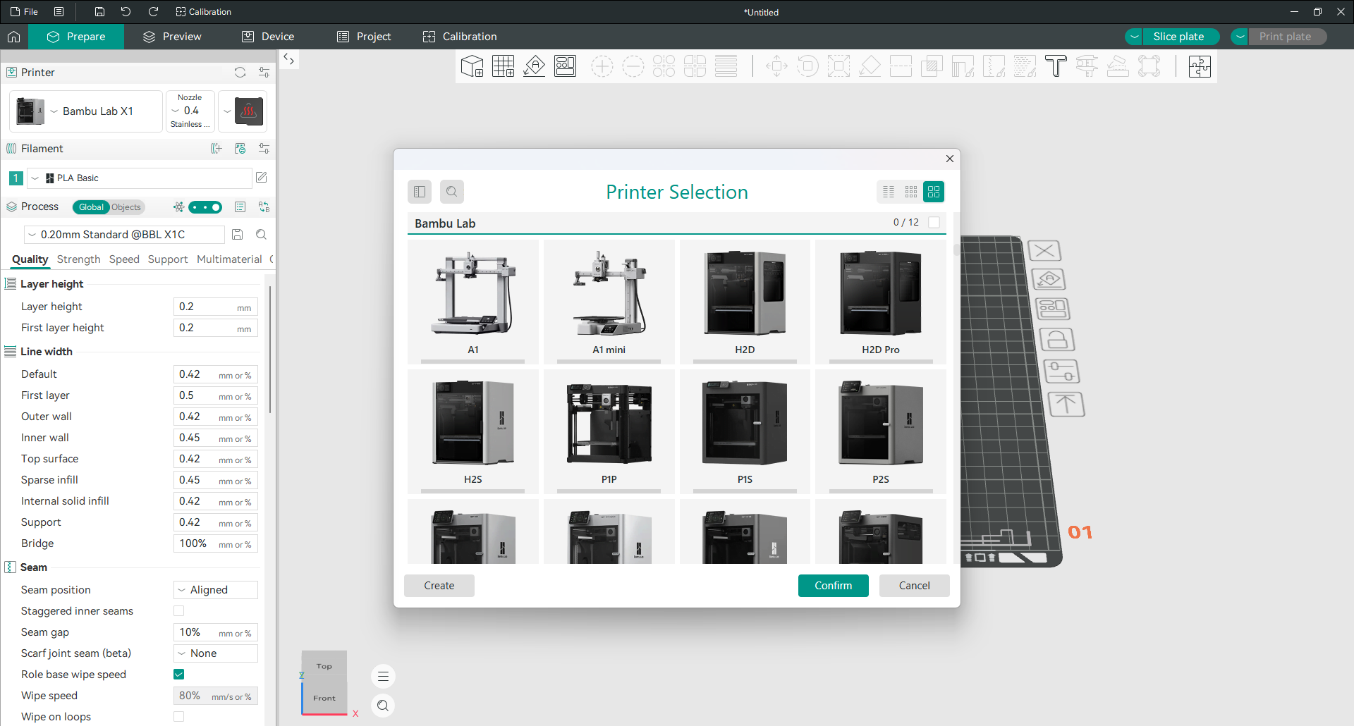
Open the printer dropdown in the left panel and choose to add a printer. Brands run down the left side of the dialog. Pick yours, and the models appear as cards. Tick the ones you own and confirm.
If your exact model is not listed, you have two options. Check whether a close relative from the same brand is there, since many printers in a range share a profile. Failing that, use the Create button to build a custom profile, which is also how you set up a printer running Klipper, Marlin, RepRapFirmware or Repetier on hardware nobody has published a profile for.
Choose the right nozzle size
A printer in Orca Slicer is a machine plus a nozzle. That is why the profile name reads like “Bambu Lab X1 Carbon 0.4 nozzle” rather than just the model name.
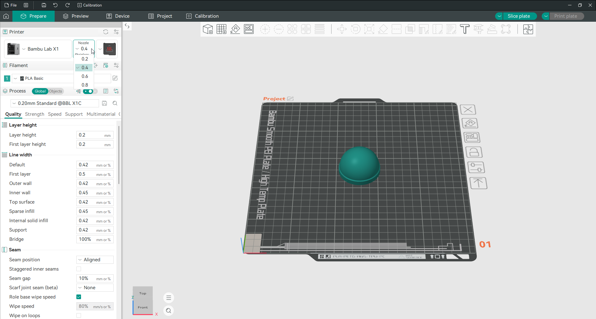
Set this to whatever is physically in your hot end. It is not a preference, it is a statement of fact, and getting it wrong throws off every line width and flow calculation downstream.
Nozzle size also sets the sensible range for your layer height. The usual rule is that layer height should sit between 25 and 75 percent of nozzle diameter:
| Nozzle | Usable layer height | Common choice |
|---|---|---|
| 0.2 mm | 0.05 to 0.15 mm | 0.10 mm |
| 0.4 mm | 0.10 to 0.30 mm | 0.20 mm |
| 0.6 mm | 0.15 to 0.45 mm | 0.30 mm |
| 0.8 mm | 0.20 to 0.60 mm | 0.40 mm |
More on this on the layer height page.
Connect Orca Slicer to a network printer
This is the step most guides skip, and it trips up more people than anything else in the program.
Click the icon next to the Printer heading in the left panel. A window called Physical Printer opens. This is where you tell the slicer how to reach your machine over the network.
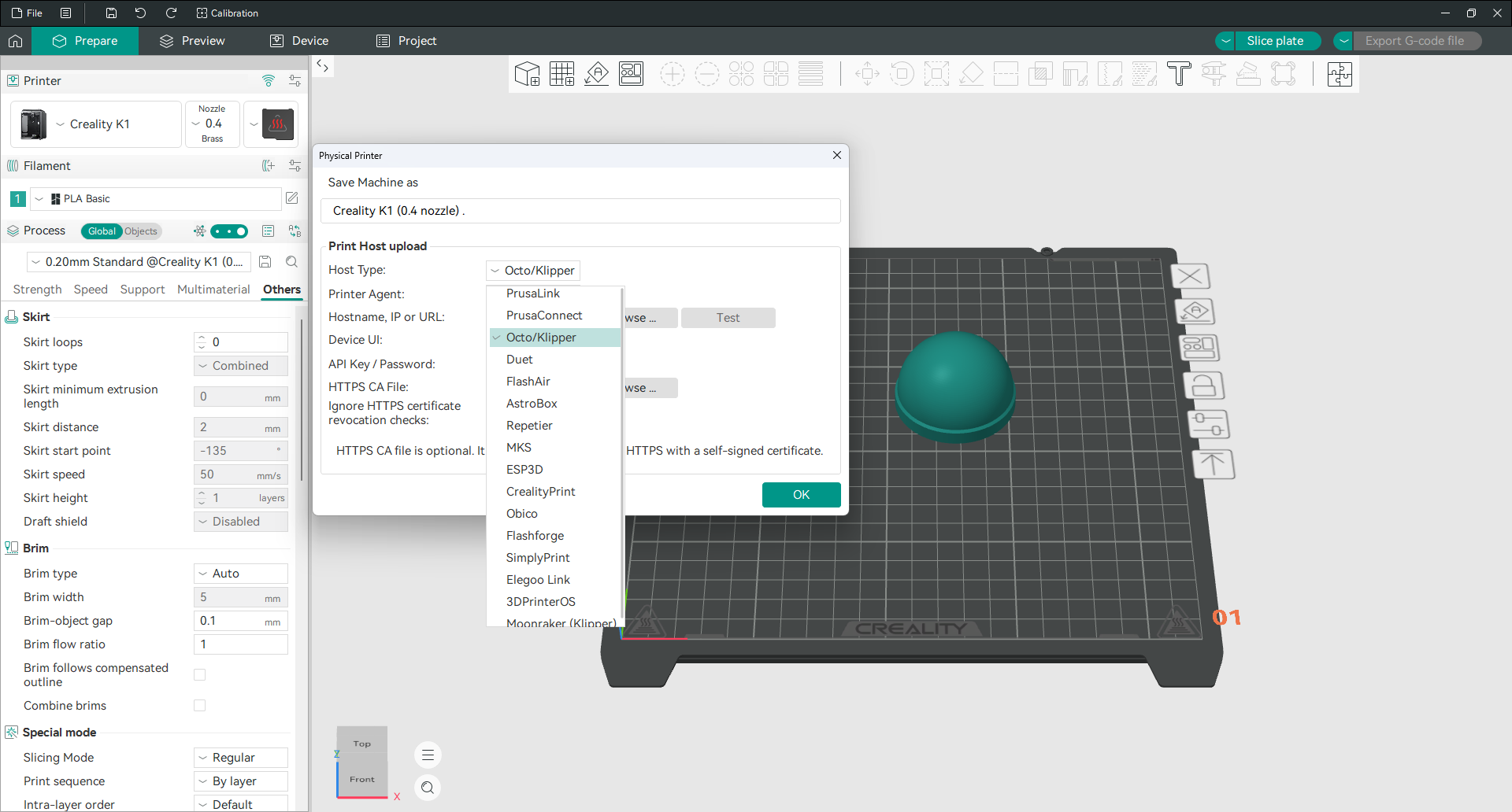
There are only a few fields that matter:
Host Type. What software is running on the printer or on the box in front of it. This is the field that decides whether anything else works.
Hostname, IP or URL. The address of the printer on your network. An IP address like 192.168.1.50 is more reliable than a hostname, because hostnames depend on your router resolving them.
API Key or Password. Most print hosts require one. OctoPrint generates it in its settings. Moonraker installs often do not need one at all on a trusted local network.
There is a Test button next to the address field. Use it. It tells you immediately whether the connection works, which saves you slicing a whole plate before discovering it does not.
Which Host Type should you choose
Picking the wrong Host Type is the single most common reason uploads fail, and the error message rarely says so. OrcaSlicer defaults to Octo/Klipper, and that default is right often enough that people assume it is always right.
Match your setup to the list:
| What you are running | Host Type to pick |
|---|---|
| OctoPrint | Octo/Klipper |
| Klipper with Mainsail or Fluidd | Octo/Klipper, or Moonraker (Klipper) |
| Prusa printer over the local network | PrusaLink |
| Prusa printer over the internet | PrusaConnect |
| Duet board with DWC | Duet |
| Creality with their own host software | CrealityPrint |
| Elegoo network printers | Elegoo Link |
| Flashforge network printers | Flashforge |
| Repetier Server | Repetier |
| Obico monitoring service | Obico |
| SimplyPrint cloud service | SimplyPrint |
The list also carries FlashAir, AstroBox, MKS, ESP3D and 3DPrinterOS for older or more specialised setups.
One point that catches Klipper users out. Octo/Klipper talks to the printer through a web interface, while Moonraker (Klipper) talks to the API directly. If you are on Linux with an Nvidia graphics card and the program keeps crashing, that difference is the cause, and the troubleshooting page has the exact fix.
Use Orca Slicer with a Bambu Lab printer
Bambu machines do not use the Physical Printer dialog. They connect through Bambu’s own network layer instead, so you pair the printer rather than typing in an address.
Add the printer as normal, then open the Device tab. Sign in to your Bambu account, or put the printer into LAN Only mode and enter its access code, which the machine displays on its own screen. Once paired, the Device tab shows live status and the top right button reads Print plate, sending jobs straight to the machine.
Everything else works exactly the same way. You get the calibration suite, the wall and seam controls and the per object settings that Bambu Studio does not expose, while keeping the printer connection you already had.
Use Orca Slicer with a Snapmaker
Set Host Type to Octo/Klipper and add :8080 to the end of your printer’s IP address. That port number is the whole trick, and leaving it off is why most people’s first attempt fails.
So if the machine’s screen shows 192.168.1.42, the field needs 192.168.1.42:8080. Press Test, then send jobs with Print, or Upload and Print, from the top right.
This works on the Snapmaker 2.0, Artisan, J1 and J1s once the printer is on current firmware. Older firmware could not talk to the slicer directly at all and had to pass files through Snapmaker’s own Luban software first. If Test keeps failing, update the printer firmware before you change anything else.
Snapmaker also publishes Snapmaker Orca, its own build of this slicer with their machines and profiles already set up, plus remote monitoring and camera control. It is tuned for the U1 in particular, and it adds a multi colour mode that gets a wide range of shades out of only four loaded filaments. Direct machine connection for the Artisan, 2.0, J1 and J1s is still being added to that build.
Which should you use? If you own a U1, Snapmaker’s build gives you the most out of the machine today. For every other Snapmaker, the standard release plus the port trick above does the job, and you get new features as soon as they ship rather than waiting for the fork to catch up.
If nothing on the network works, slicing and exporting to a USB stick always works. Nothing about that path depends on firmware.
No network? Print from SD card or USB
Plenty of printers have no network at all, and OrcaSlicer handles that without complaint.
Slice the plate, then look at the button in the top right. When there is no way to send the file, that button reads Export G-code file instead of Print plate. Click it, save the file to your SD card or USB stick, and carry it to the machine.
This surprises people who switch from a Bambu printer to something else and think a feature has broken. It has not. The button simply reflects what your current printer can actually do.
Machine start and end G-code
Every print begins and ends with a block of commands the slicer inserts for you. Heating the bed, homing the axes, wiping the nozzle, and at the end, parking the head and turning off the heaters.
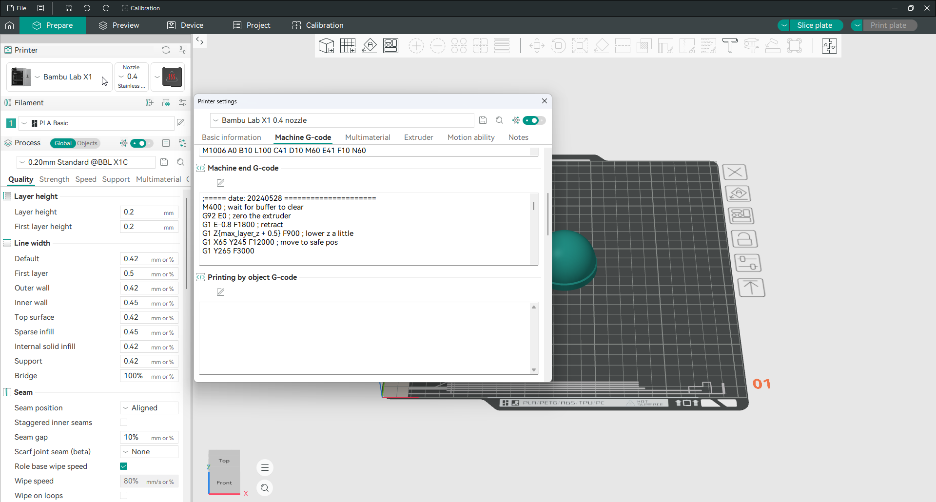
You will find these in printer settings, on the Machine G-code tab. The blocks are Machine start G-code, Machine end G-code and Printing by object G-code.
If your printer works with the supplied profile, leave these alone. You would edit them to add a purge line, to call a Klipper macro like PRINT_START, or to change what happens when a print finishes. Copy the existing block somewhere safe before you change it, because a broken start block usually means a failed first layer.
Working with models
Import a model
Drag a file onto the build plate, or use File then Import.
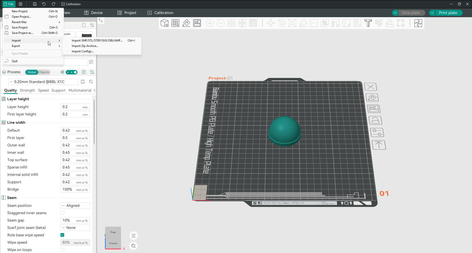
OrcaSlicer opens 3MF, STL, STEP, SVG, OBJ and AMF files. Two of those are worth calling out. STEP files carry real geometry rather than a triangle mesh, so they slice more cleanly and you can rescale them without the surface going faceted. SVG files get pulled in as flat shapes and extruded, which is a quick way to turn a logo into a printable object.
The same menu has Import Zip Archive, for model packs downloaded as a single file, and Import Configs, for loading settings someone has shared with you.
Move, scale and rotate
Select the model, then pick the move, scale or rotate tool from the toolbar. Each one gives you a panel with real numbers rather than making you drag by eye.
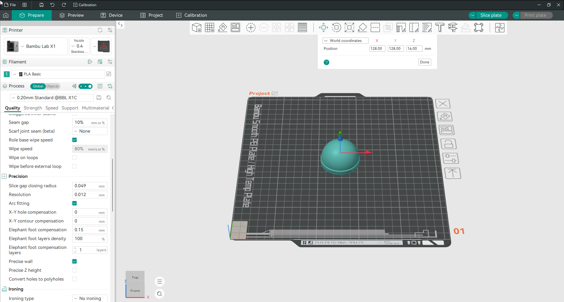
The move panel shows the object’s position in millimetres. There is a dropdown at the top that switches between world coordinates, measured from the plate, and object coordinates, measured from the model itself. World coordinates are what you want when you are placing things on the plate.
You can also drag the coloured arrows in the 3D view. Type numbers when you need precision, drag when you are just arranging.
Duplicate a model and fill the plate
Right click the model. Add instance gives you one more copy. Set number of instances lets you say how many you want. Fill bed with instances packs as many as will fit.
Instances are copies that stay linked, so changing a setting on one changes all of them. If you want copies that behave independently, use Clone instead, or choose Set as Individual Objects to break an existing set apart.
Arrange and orient models automatically
Two toolbar buttons do most of the plate tidying for you.
Auto arrange spaces every object on the plate so nothing collides and skirts do not overlap. Press it after loading several models rather than dragging them around by hand.
Auto orientation rotates each object to the position that needs the least support. It is a good first guess, not a final answer, so check the result before you slice.
There is also Lay on face in the toolbar. Click it, then click any flat face on the model, and that face is placed down on the plate. This is the fastest way to get a cut piece or an awkward part sitting the right way up.
Split a model into objects or parts
Some downloaded files contain several separate pieces bundled into one object. Splitting separates them so you can move each one on its own.
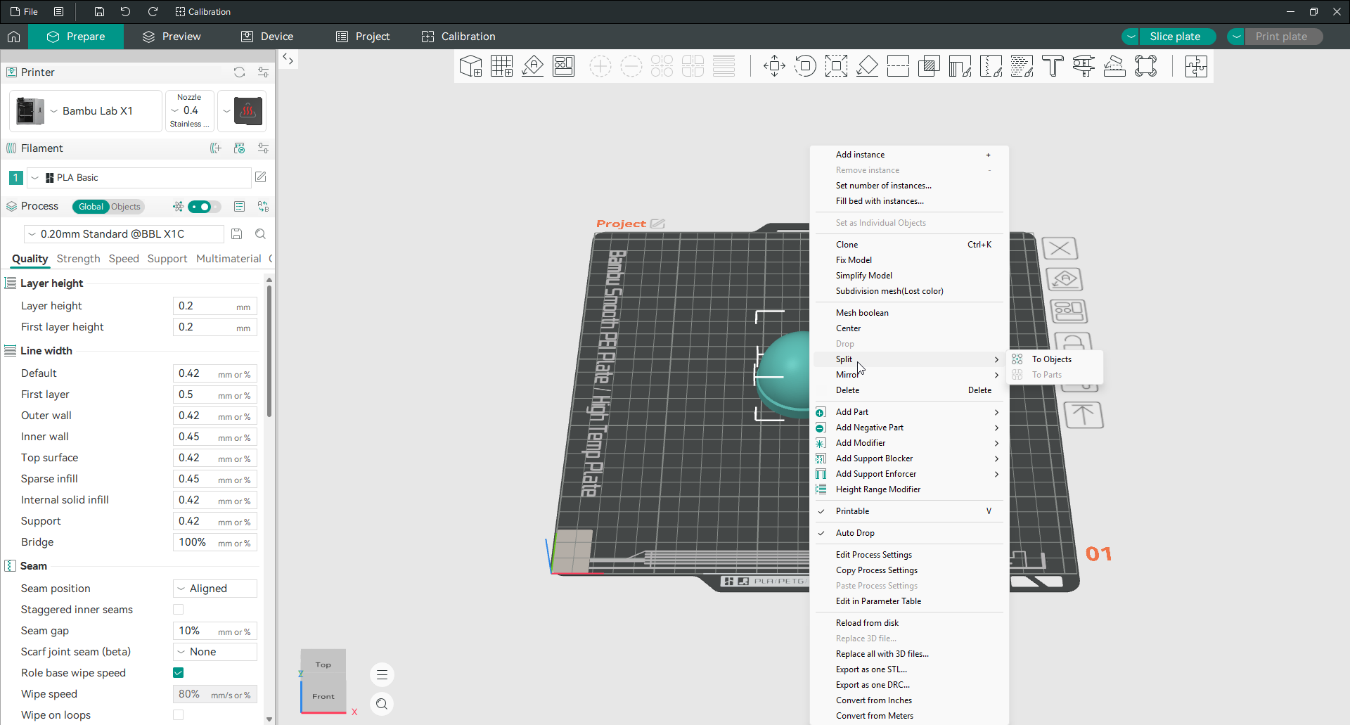
Right click the model and choose Split. There are two options and the difference matters.
To Objects breaks the file into fully independent objects. Each one can be moved, rotated and deleted on its own, and each can have its own settings.
To Parts keeps everything as one object but separates the shells inside it. This is what you want when a model was designed as a multi colour piece, because you can then assign a different filament to each part.
Mirror a model
Right click, choose Mirror, then pick an axis.
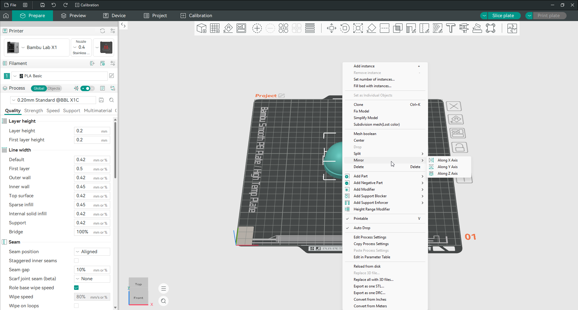
Mirroring along X or Y gives you the opposite hand of a part, which is how you get a left version of something modelled as a right. Mirroring along Z flips it upside down, though rotating is usually the clearer way to do that.
Cut a model into pieces
Cutting is how you print something taller or wider than your build plate, and how you split a model so the tricky face lies flat.
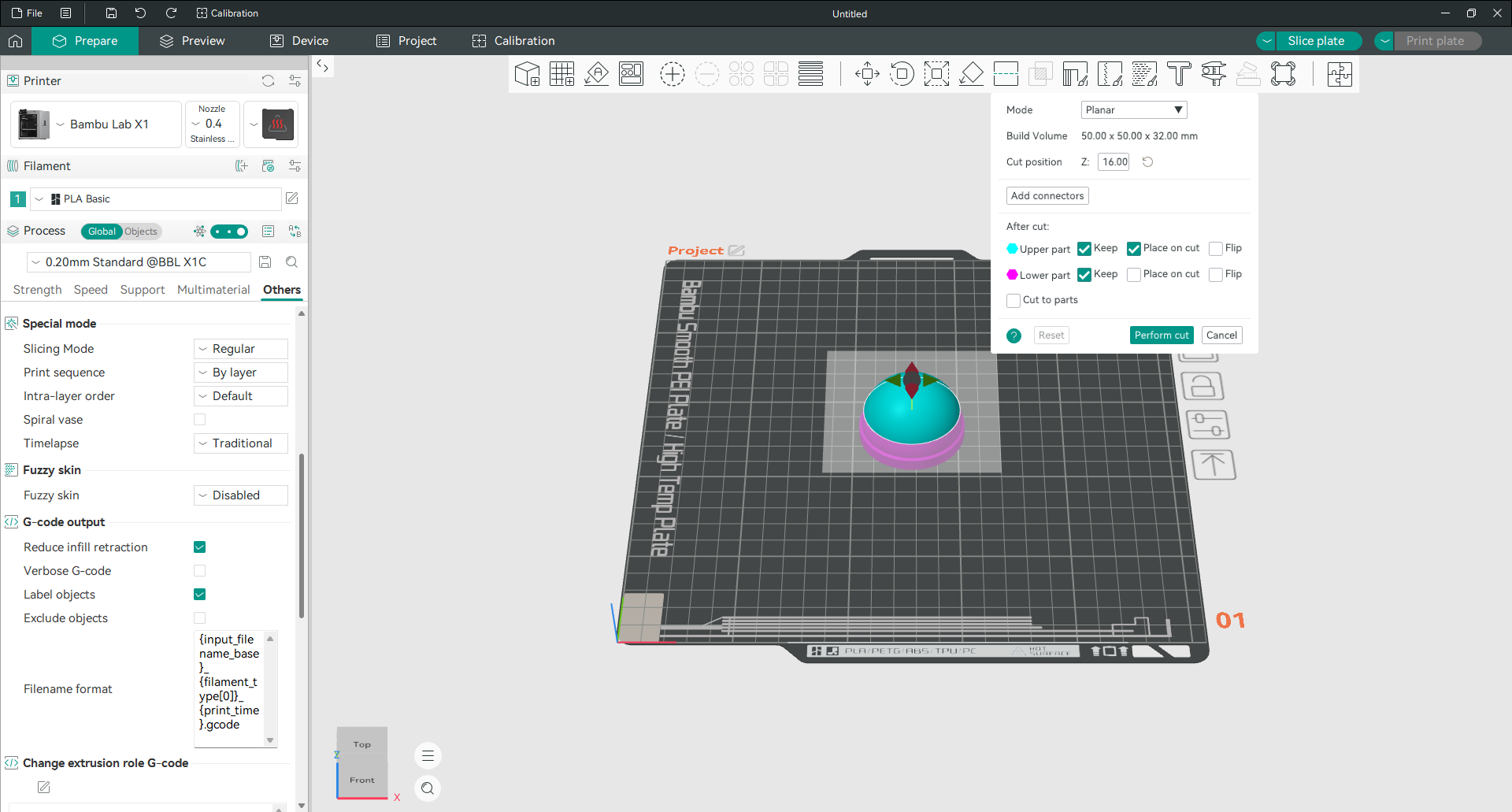
Select the model and open the cut tool. Set the height of the cut with the Z field, or drag the plane in the 3D view. Then decide what happens afterwards:
Keep controls whether each half survives the cut. Untick one and you print only the other.
Place on cut lays a piece down with the cut face on the plate. This is usually what you want, because a flat face on the plate needs no supports.
Flip turns a piece over, for when the cut face is not the side you want down.
Add connectors is the part worth learning. It cuts matching pins into one half and matching holes into the other, so the pieces line up when you glue them.

Place three or four connectors around the cut rather than one in the middle. One connector lets the halves pivot, several lock the alignment.
Measure a model
The measure tool answers the question every printer asks at some point, which is whether this thing will actually fit.
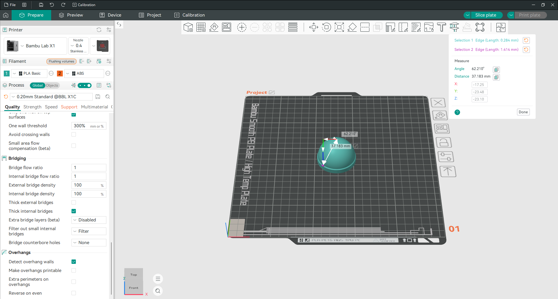
Open the tool, click one feature on the model, then click another. It labels what you picked, gives you the distance between them, the angle, and the difference along each axis separately. Every value has a copy button next to it.
It works on edges, faces and points, so you can measure the diameter of a hole, the angle of an overhang, or the gap between two features, without going back to your CAD program.
Fix a model that will not slice
If a model slices strangely, with missing walls or solid areas where there should be holes, the mesh is usually broken rather than the slicer.
Right click and choose Fix Model. OrcaSlicer attempts a repair and tells you what it found. Simplify Model is the other one worth knowing, for files with far more triangles than they need, which slow everything down for no visual benefit.
If a repair does not work, the troubleshooting page covers what to try next.
Use the object list and per plate settings
Switch the left panel from Global to Objects and it turns into a tree of everything on your plate.
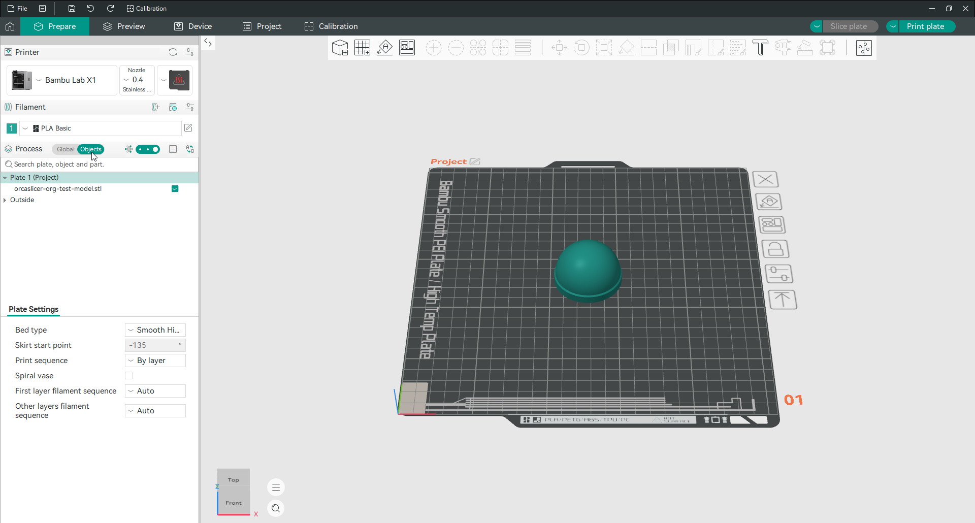
Every model on the plate is listed by filename, with a checkbox that controls whether it prints. There is a search box at the top, which earns its place once you have twenty objects loaded. Anything sitting outside the printable area gets grouped under Outside, which is a quick way to spot a model that has drifted off the plate.
Below the tree is a panel most people never notice: plate settings. Bed type, skirt start point, print sequence, spiral vase and filament sequence can all be set here, and they apply to that plate alone.
That matters if you use several plates in one project. You can print one plate on a textured sheet and another on a smooth one, or run one plate object by object and the next layer by layer, without touching your global settings at all.
Preparing the print
Choose your build plate type
Tell Orca Slicer which sheet is on your printer, because filament profiles set bed temperature per plate type.
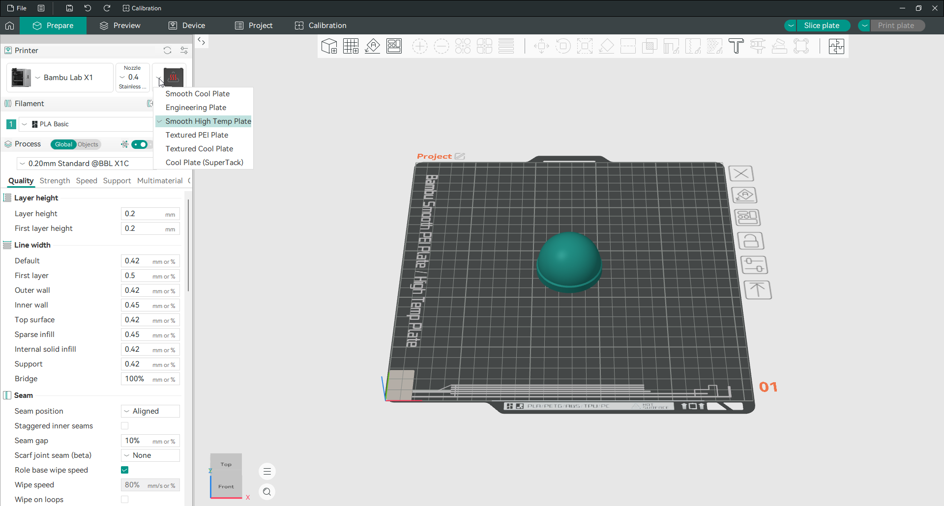
Click the plate icon next to the nozzle and pick your surface. The same PLA profile will run the bed at one temperature on a cool plate and a noticeably higher one on a textured PEI sheet, because those surfaces need different heat to grip properly.
Getting this wrong is a common cause of prints that either will not stick or weld themselves to the sheet. Full detail is on the multiple bed types page.
Add a brim
A brim is a flat collar printed around the base of your model. It adds surface area, which keeps small or tall objects from letting go partway through.
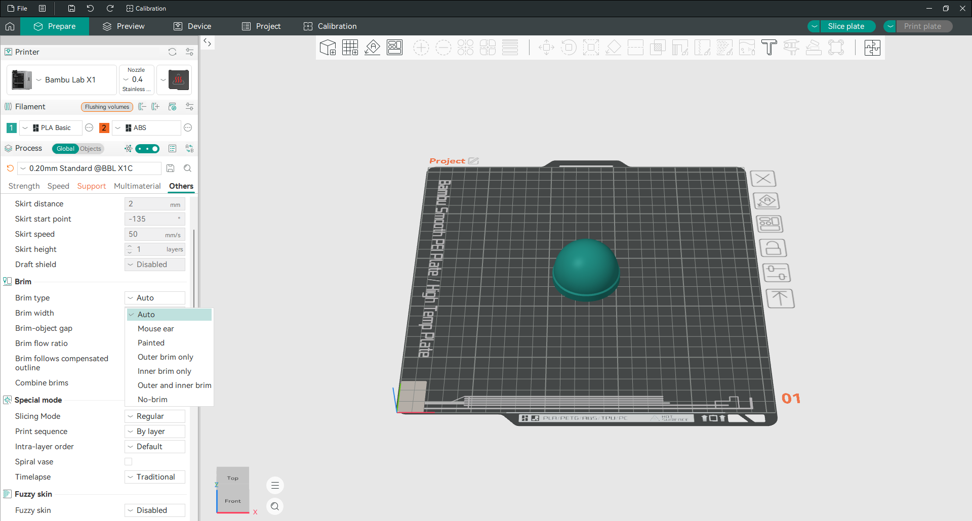
You will find it in the Others tab under Brim. There are seven types, and most guides only mention three of them.
Auto is the default and decides for itself whether the model needs one.
Outer brim only puts the collar around the outside. This is the standard choice.
Inner brim only puts it inside holes and enclosed areas instead, for parts whose weak point is an internal feature.
Outer and inner brim does both, for the most stubborn cases.
Mouse ear prints small discs at the corners rather than a full collar. Corners are where lifting starts, so this gives you most of the benefit with a fraction of the material and almost nothing to clean up afterwards.
Painted lets you brush the brim on by hand, exactly where you decide it is needed.
No-brim turns it off completely.
Brim width defaults to 5 mm, which is plenty for most parts. Brim object gap is the small clearance between the brim and the model, and raising it slightly makes the brim easier to snap off at the cost of a little grip.
Add a raft
A raft is a full platform printed underneath the model rather than a collar around it. Set Raft layers in the Support tab to anything above zero to turn it on.
Rafts use more filament and more time than brims, and they leave a rougher underside. Reach for one when the plate itself is the problem, on a warped or badly worn surface, or with a material that refuses to stick no matter what. For everything else a brim does the job with less waste.
Add supports
Supports hold up parts of a model that would otherwise be printed into thin air.
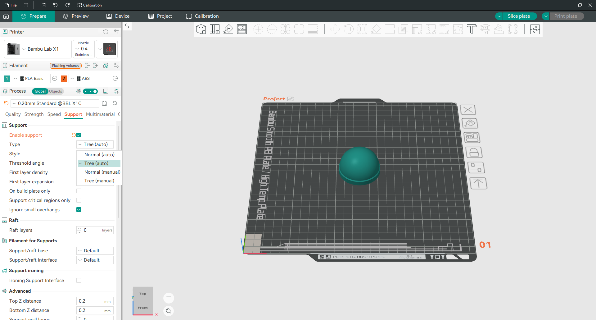
Open the Support tab and tick Enable support. Then choose a type, and note that OrcaSlicer defaults to Tree (auto), not the grid style most slicers start with.

Normal builds a straight grid up from the plate. It is strong, predictable, and holds anything, but it uses more material and touches more of your model, so it leaves more marks.
Tree grows branches that reach up to only the points that need holding. Far less material, far easier to remove, and much kinder to curved surfaces. It can struggle with large flat overhangs, where the grid is still the better answer.
The auto versions place supports for you. The manual versions place none, leaving you to paint them on yourself.
Threshold angle decides what counts as an overhang and defaults to 30 degrees. Lower it and you get fewer supports, raise it and you get more. Top Z distance sets the gap between the support and the model above it, and it is the setting to adjust if supports either fuse to your part or fail to hold it.
Paint supports by hand
Automatic supports are cautious. They often add material where nothing was needed, and occasionally miss a spot that mattered.
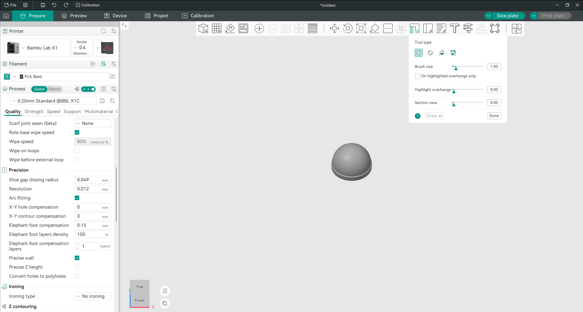
Set support type to one of the manual options, then open the support painting tool. Paint enforcers where you want support and blockers where you do not.
Two controls make this much easier. Highlight overhangs shades the parts of the model that actually need holding, so you are not guessing. Section view cuts away the front of the model so you can paint inside cavities you would otherwise never reach.
Set filament temperature
Click the edit icon next to your filament to open its settings.
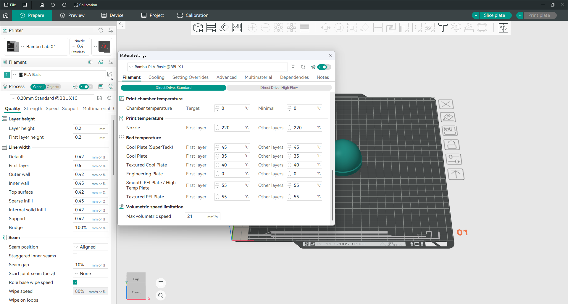
Nozzle temperature has separate values for the first layer and every layer after it. Bed temperature is listed once per build plate type, which is why choosing the right plate earlier actually matters.
Change these when you switch brands rather than materials. Two spools both labelled PLA can want temperatures 15 degrees apart. If you are not sure what yours wants, the temperature tower in the calibration menu finds the answer in one print.
Max volumetric speed sits on the same tab and is the real limit on how fast you can print a given filament. It caps how much plastic can be melted per second, no matter what your speed settings say.
Change filament colour
Click the numbered square next to the filament name.
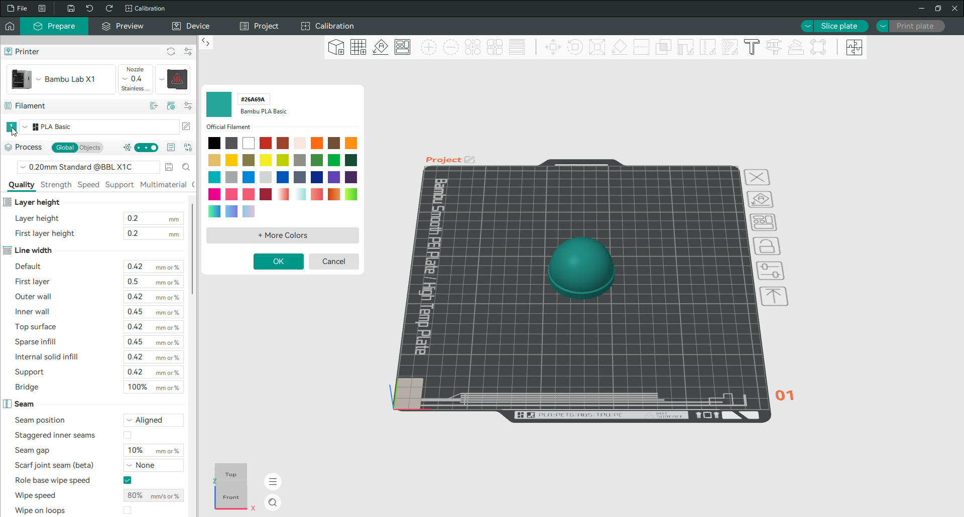
Pick from the palette, or use More Colors to enter an exact value. This changes nothing about how the model prints. It only changes what you see on screen, which becomes genuinely useful the moment you are running more than one filament and need to tell them apart.
Paint a model in more than one colour
Load a second filament first, using the plus icon next to the Filament heading. The colour painting tool needs at least two to work with.
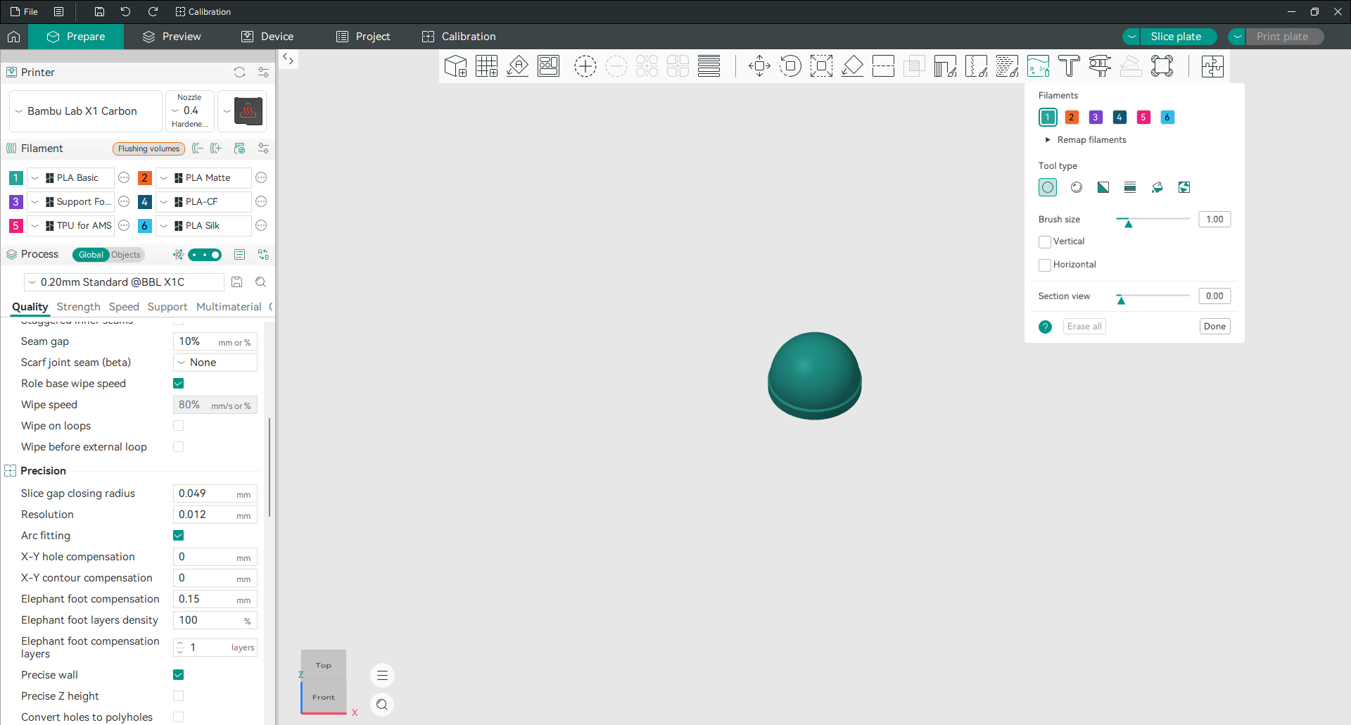
Open the tool from the toolbar. Your filaments appear as numbered chips along the top. Click a chip to select it, then paint on the model.
There are five painting tools, and picking the right one saves a lot of clicking:
Circle paints a round patch wherever you drag. This is the everyday brush.
Sphere looks the same but paints through the model. Anything inside the ball of the cursor gets coloured, including surfaces you cannot see, which is what you want on a thin wall you need coloured on both sides.
Triangle paints one face of the mesh at a time. Slow, but exact.
Height Range colours everything between two heights, even across separate parts of the model. This is how you get clean horizontal colour bands without painting a single stroke.
Fill floods one connected area in a single click, stopping where the surface changes direction. This is how you colour a face or a raised logo without tracing its edge.
Turn on Gap Fill and set a gap area size, and small unpainted specks left behind by your strokes get filled in automatically. Without it, painted areas often end up peppered with tiny holes that cost you extra filament changes.
Once you have more than one filament loaded, a Flushing volumes button appears next to the Filament heading. That is where you control how much plastic gets purged during each colour change, and it has a real effect on both waste and print time.
Slice and read the preview
Click Slice plate, then switch to the Preview tab.
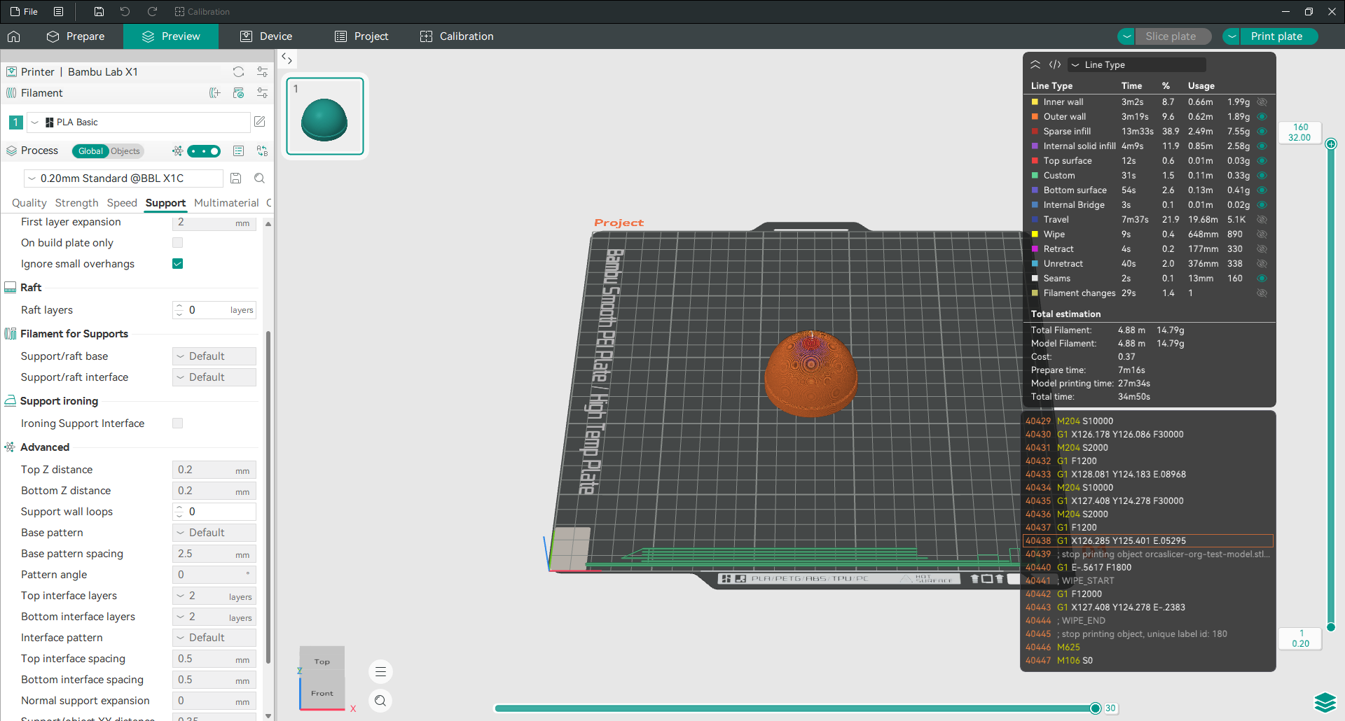
This is the last chance to catch a problem before you commit filament to it. Drag the slider on the right to move through the layers and look for anything obviously wrong: a first layer that does not cover, supports touching a surface you care about, gaps in the top skin.
The dropdown at the top right changes what the colours mean. Line type is the useful default, colouring each feature so you can tell walls from infill from supports. There are also views for speed, flow and pressure advance.
The panel below gives you total time, split into preparation and actual printing, plus how much filament the job needs by length and weight, and its cost. That breakdown is listed per feature, so you can see exactly what is eating your time. Supports taking a third of your print is a good reason to go back and paint them by hand instead.
Changing settings
Where the settings live
Print settings sit in the lower half of the left panel, split across six tabs. Once you know which tab owns which job, finding anything takes seconds.
| Tab | What it controls |
|---|---|
| Quality | Layer height, line width, seams, ironing, precision, bridging, overhangs |
| Strength | Walls, top and bottom shells, infill |
| Speed | How fast every kind of line is printed |
| Support | Supports, raft, support filament |
| Multimaterial | Prime tower, flushing, filament per feature |
| Others | Skirt, brim, special modes, fuzzy skin, G-code output |
There is a search box above the tabs. Type any setting name into it and OrcaSlicer takes you straight there, which beats hunting through six tabs when you only half remember what something is called.
Remember that the tabs only show what your current mode allows. If a setting described here is missing, switch to Advanced or Expert first.
Change layer height
Layer height is in the Quality tab, right at the top. It sets how thick each printed layer is, and it is the single biggest trade between speed and surface finish.
Thinner layers give smoother curves and take longer. Thicker layers finish sooner and show more visible stepping. Keep the value between 25 and 75 percent of your nozzle diameter, and prefer numbers that divide cleanly into your printer’s Z steps.
First layer height sits directly below and is usually set a little thicker than the rest. A fatter first layer squashes into the plate better and forgives a bed that is not perfectly level. There is much more detail on the layer height page.
Change infill density and pattern
Infill is the structure inside your model. Both controls are in the Strength tab.
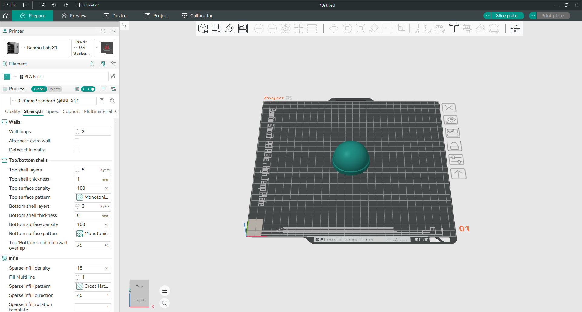
Sparse infill density is a percentage. The default is 15 percent, which is right for most decorative and light duty parts. Going above 40 percent rarely adds much strength for the filament it costs, because past that point extra walls do more good than extra infill.
Sparse infill pattern decides the shape of that internal structure. Grid and gyroid are the common all rounders. Cross hatch is the default here. Honeycomb and cubic are stronger in more directions and take longer.
Two patterns are worth knowing about specifically. Gyroid is equally strong in every direction and prints without the nozzle ever crossing its own path. Tri-hexagon avoids intersections entirely and rotates every layer, which spreads strength evenly through the part.
For strength, raise wall loops in the same tab before you raise infill. Walls carry load far better than the material inside them. The walls and surfaces page covers this properly.
Change wall thickness
Wall thickness is set by wall loops, not by a millimetre value. Two loops of a 0.42 mm line gives you roughly a 0.84 mm wall.
The default is two. Three is a sensible step up for anything functional. Beyond four you are usually better off adding infill instead.
The wall generator on the Quality tab decides how those loops are calculated. Classic gives every wall the same width. Arachne varies the width so thin features get filled properly instead of being skipped. Classic is the default. The wall generator page explains when to switch.
Change print speed
Every type of line has its own speed, which is why the Speed tab looks long.
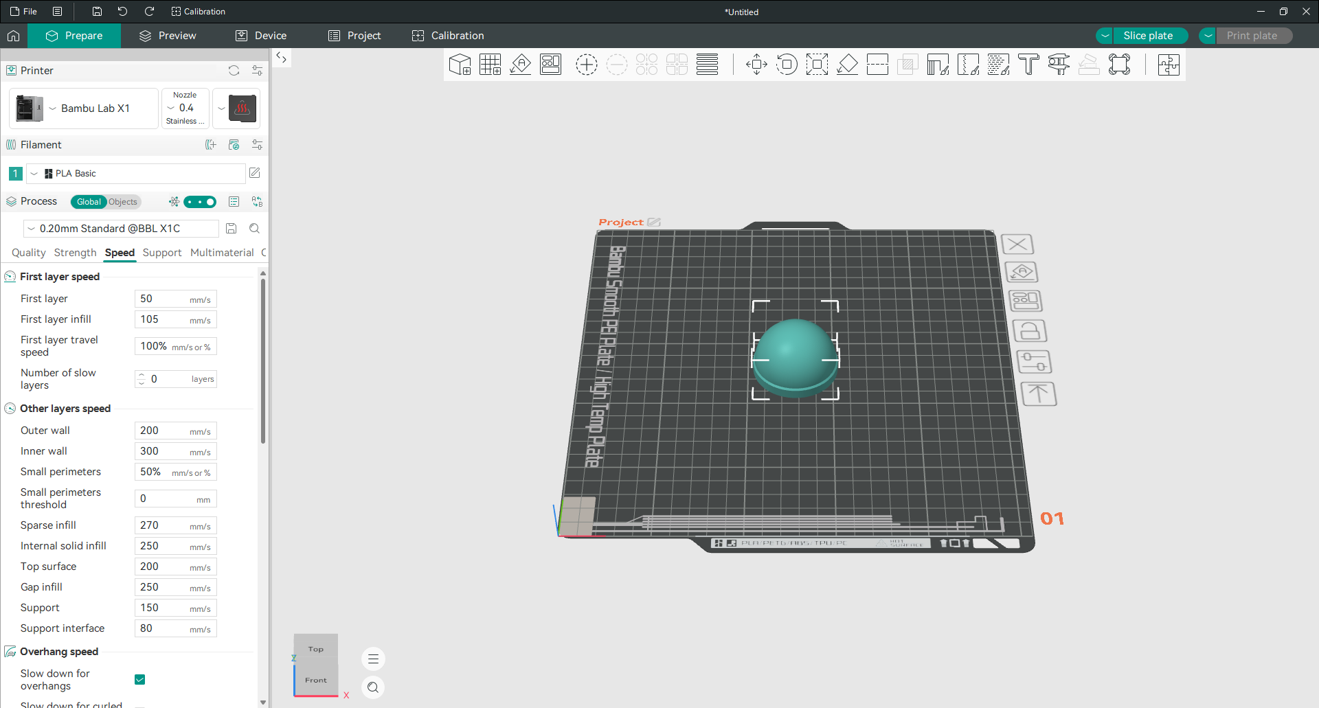
The ones that matter most:
First layer is deliberately slow, because a first layer that goes down well saves the whole print. Leave it slow.
Outer wall is the speed that shows. Everything a person sees and touches is printed at this speed, so it is set lower than the inner wall on purpose.
Inner wall and sparse infill are hidden, so they run much faster.
Support runs slower than infill because support has almost nothing underneath it to hold on to.
Before you raise anything, check max volumetric speed in your filament settings. That value caps how much plastic your hot end can actually melt per second. Push the speed sliders past it and the printer simply slows itself down, or worse, under extrudes and you get gaps.
Use variable layer height
Variable layer height lets one object print with thin layers where the surface is curved and thicker layers where it is straight. You get the finish of a fine print for much less time.
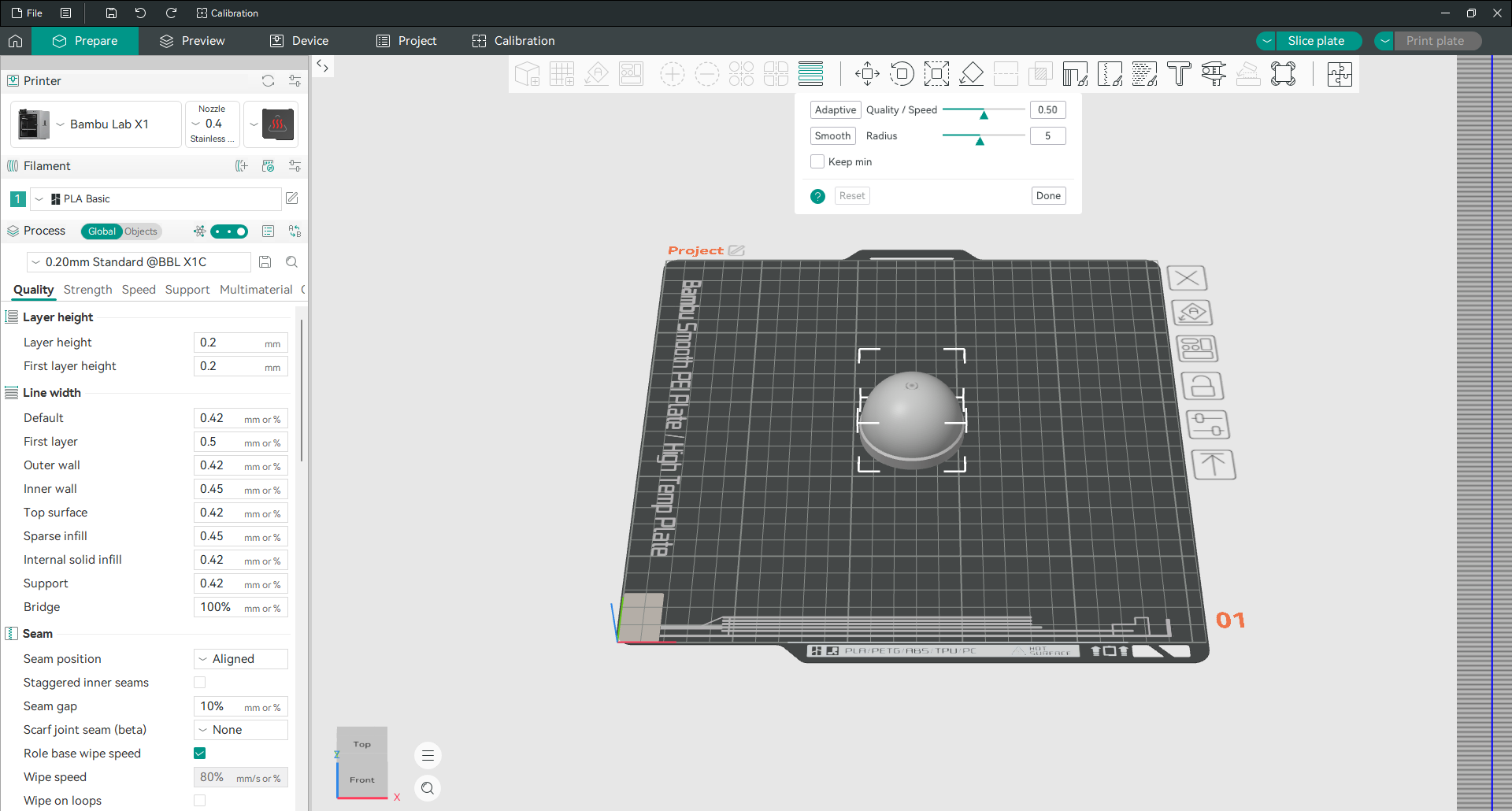
Select the object, open the tool from the toolbar, then click Adaptive. The quality and speed slider decides how aggressive it is. Move it toward quality and more of the model gets thin layers. Smooth blends the transitions so you do not see a hard line where the layer height changes, and the radius controls how wide that blend is.
You can also paint the profile yourself. The bar beside the model responds to clicks: left click makes layers thinner at that height, right click makes them thicker.

The published example on a sphere removed the visible stepping on the dome and cut print time by nearly 28 percent at the same time. Curved and domed shapes are exactly where this pays off. On a box with flat sides it does nothing useful.
One limitation to know about. If you are printing with more than one colour or material, every object on the plate has to share the same layer height, so variable layer height is unavailable.
Print in vase mode
Vase mode prints an object as one continuous spiral with a single wall and no infill. The Z axis rises constantly instead of stepping, so there is no layer seam anywhere on the part.
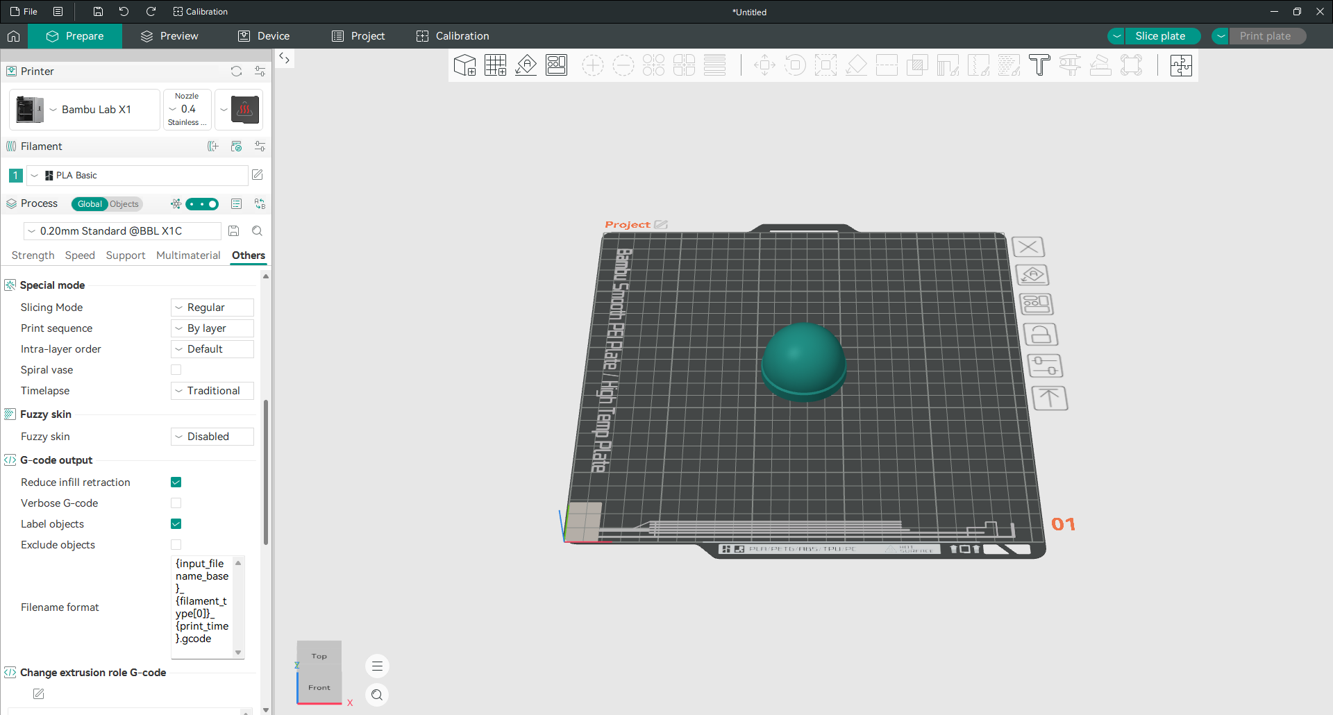
Tick Spiral vase in the Others tab under Special mode.
It only works on models that are a single unbroken shell with no roof, which is why vases, cups and lampshades are the usual subjects. If your model has a lid, an internal wall or several separate pieces, the option will either refuse or produce something you did not intend.
Since the wall is a single line, its thickness comes from your line width setting rather than wall loops. Widen the line if you want a sturdier result.
Save your own preset
Once you have a combination that works, save it so you never rebuild it.
Change whatever you need, then click the save icon next to the preset name. Give it a name that says what it is for rather than what you changed, because in six months “0.20mm PETG brackets” will mean something to you and “0.20mm Standard copy 3” will not.
Presets are stored per printer. A process preset saved for one machine will not appear when you switch to another, which is deliberate, since speeds and temperatures rarely transfer between printers.
Working with G-code
Add a pause at a layer
A pause stops the print at a layer you choose. That is how you get a two colour print out of a single nozzle machine, or drop a magnet or a nut into a cavity before it gets sealed over.
Slice the plate and switch to Preview. Find the layer where you want the pause on the vertical slider, then right click the slider handle.
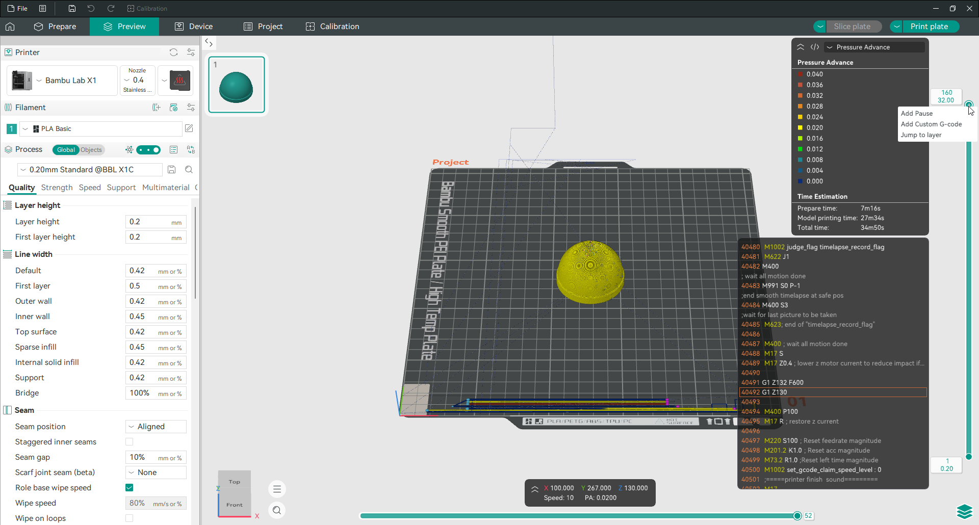
Choose Add Pause. A marker appears on the slider showing where the print will stop.
Pick your layer carefully. The pause happens before the layer you selected is printed, so if you want a colour change to appear from layer 40 upward, set the pause at layer 40, not 39. Scrub through the preview and confirm the marker sits where you expect before you export.
When the printer reaches that point it stops and waits. Change the filament, then resume from the printer’s own controls.
Insert custom G-code at a layer
The same right click menu has Add Custom G-code, which drops any commands you like at that exact layer.
This is how you do things a pause cannot. Change the nozzle temperature partway up for a filament that behaves better hot at the bottom. Drop the fan speed for a run of bridges. Fire a Klipper macro. Move the head out of the way so you can photograph the inside of a part.
Keep these snippets short and test them on a small object first. A command that puts the head somewhere unexpected can crash it into the print.
Jump to a layer
The third item on that menu is Jump to layer. Type a number and the preview goes straight there.
It sounds trivial until you are checking a print that is two thousand layers tall and you know the problem is somewhere around layer 1,180. Dragging to it by hand is hopeless.
Export G-code
If your printer is connected, the button in the top right sends the job straight to it. If it is not, that button reads Export G-code file and saves the sliced result to disk instead.
File then Export holds the rest of the options. Export plate sliced file has a keyboard shortcut, which is worth learning if you export often. There are also options to export the models themselves as STL, 3MF or DRC, and to export the toolpaths as an OBJ once the plate has been sliced.
Save G-code straight onto the SD card or USB stick you are going to use. Copying it afterwards is where people accidentally send an old version to the printer.
Read the time, filament and cost estimate
After slicing, the preview panel tells you what the job will actually cost you before you commit to it.
You get prepare time and model printing time listed separately, then a total. You get filament use by length and by weight. And you get a price, if you have told OrcaSlicer what your filament costs in its filament settings.
The genuinely useful part is that the breakdown is listed per feature. Seeing that supports account for a third of your print time is the fastest argument there is for going back and painting them by hand instead.
There is also a time cost field in printer settings, under Basic information, where you can enter an hourly running cost for the machine. Fill it in and the estimate stops being only about filament and starts telling you what a print is really worth, which matters if you print for other people.
Managing OrcaSlicer
Update Orca Slicer
Open the menu icon next to File, go to Help, and choose Check for Updates.
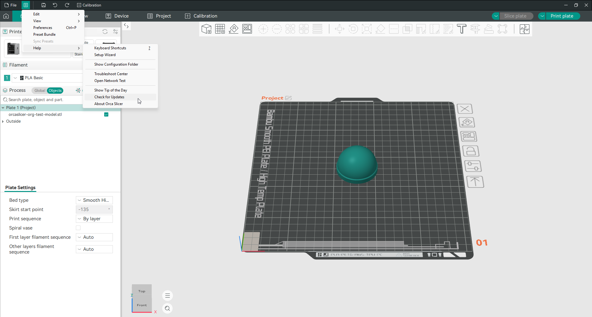
If you installed from the Microsoft Store or from Flathub, your package manager handles updates and you can ignore this.
One thing worth clearing up, because plenty of guides get it wrong: there is no beta channel. There are stable releases and there are nightly builds, and that is it. Nightlies carry the newest work and the newest bugs, so run one only if you are chasing a specific fix or reporting a problem. If a page tells you to install the latest beta, that page is out of date.
The same Help menu holds a few other useful doors: Setup Wizard runs the first time setup again, Show Configuration Folder opens the folder your settings live in, and Troubleshoot Center collects the built in diagnostics.
Back up and move your profiles
Everything you have customised can be packed into one file.
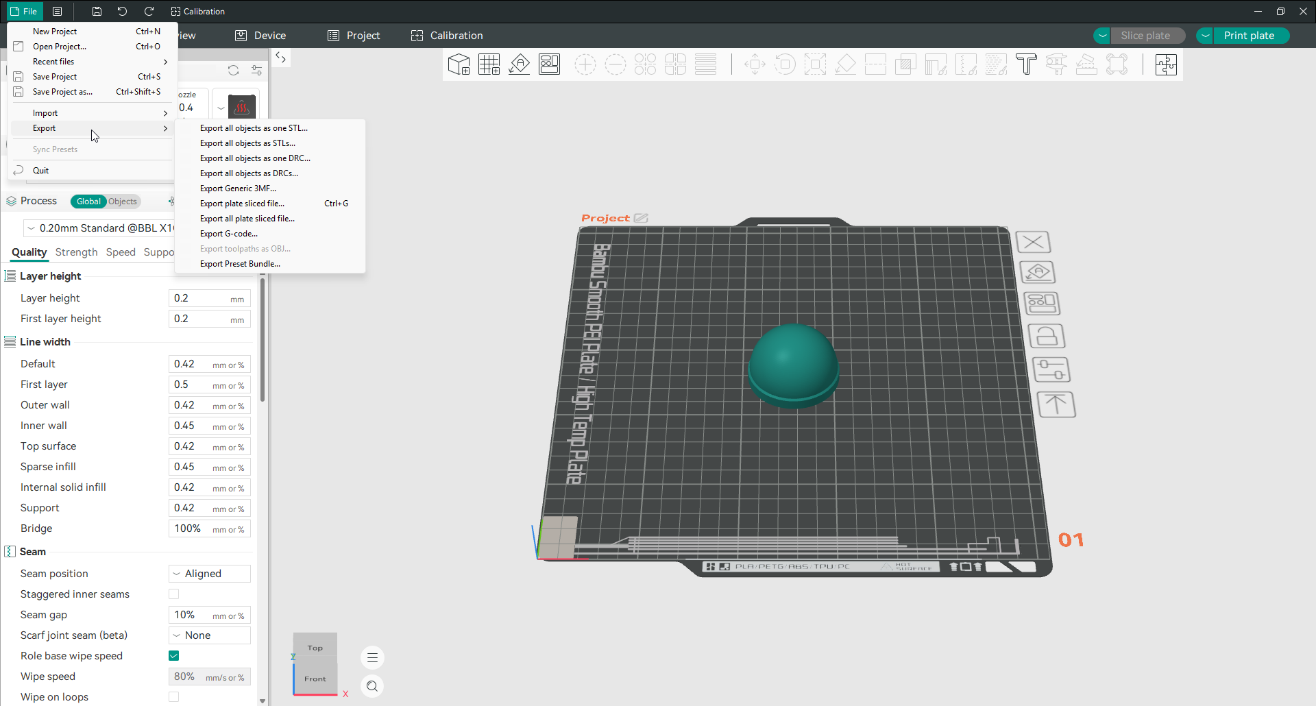
Go to File, then Export, then Export Preset Bundle. That single file carries your printers, your filaments and your process presets together. On the other machine, use File then Import then Import Configs to load it back.
Do this before any big update, and do it before you reinstall. It takes ten seconds and it has saved a lot of people a lot of rebuilding.
Where OrcaSlicer stores your profiles
On Windows the folder is %APPDATA%\OrcaSlicer. Paste that into the address bar of any Explorer window and it will open. On macOS and Linux the equivalent folder is reached fastest through Help then Show Configuration Folder.
Inside you will find user holding your own presets, system holding the shipped ones, printers and plugins, a log folder, and user_backup.
That backup folder is worth remembering. If your settings ever appear to reset themselves, your previous presets are usually sitting in user_backup waiting to be copied back. The main configuration file also keeps a .bak copy alongside it. The troubleshooting page walks through recovering from both.
Run the built in calibration tests
The tests live in the Calibration entry on the top menu bar, next to undo and redo. This suite is the main reason people move to this slicer in the first place.
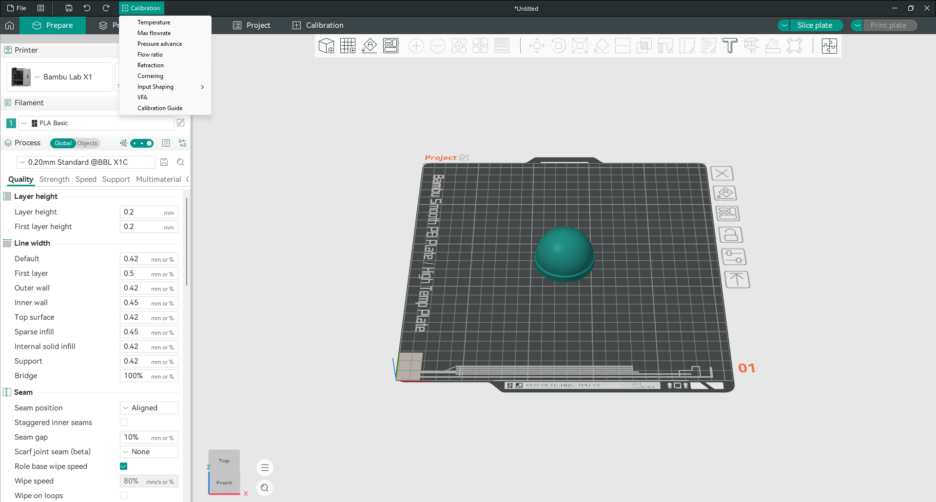
Each entry generates a test object, slices it with a range of values already applied, and asks you to read the printed result. No spreadsheet, no manual editing.
| Test | What it fixes |
|---|---|
| Temperature | Layer bonding, stringing, surface finish |
| Max flowrate | Under extrusion when printing fast |
| Pressure advance | Bulges at corners, thin patches after them |
| Flow ratio | Walls that are too thick or too thin |
| Retraction | Stringing and blobs between parts |
| Cornering | Ringing and rounded corners |
| Input Shaping | Ghosting and vibration marks |
| VFA | Fine vertical banding on flat walls |
There is also a Calibration Guide entry that explains the recommended order, and it is worth following. Temperature first, then flow, then pressure advance. Calibrating in the wrong order means measuring one problem through another. Full walkthroughs live on the calibration pages.
Set the Z offset
Z offset shifts the whole print up or down relative to the bed. It is the fix for a first layer that is squashed flat, or floating above the plate.
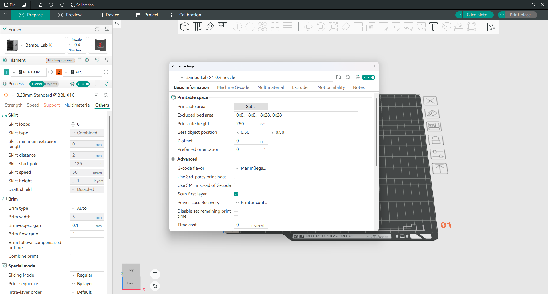
Open printer settings and stay on the Basic information tab. Z offset is in the Printable space group, between best object position and preferred orientation. The default is 0 mm. A positive value lifts the nozzle away from the plate, a negative value brings it closer.
Two things trip people up here.
First, the field is hidden in Simple mode. Turn on Advanced or Expert in the printer settings window or you will conclude the setting does not exist.
Second, this is mostly a printer job, not a slicer job. If you run Klipper, the real control is the z_offset value in your printer configuration, and the slicer field should only be used for small trims on top of it. Calibrate on the machine first.
There is no way to set a different Z offset per build plate. It was asked for and turned down, so a single value has to cover every sheet you use.
One case where this field earns its place: on Bambu A1 and A1 mini machines, editing the start G-code has no effect because the printer recalibrates itself, but the Z offset field here does work. Owners report needing somewhere around +0.2 mm on the mini and +0.35 mm on the full size A1. Change it in small steps and print a single layer square each time.
Sync your profiles with Orca Cloud
Orca Cloud keeps your profiles in sync between computers. It backs them up too, and keeps a version history, so a profile you have broken can be rolled back.
It also carries shared bundles. A bundle packages related profiles together with a description and update history, and you can publish one or subscribe to somebody else’s and receive their updates automatically. Plugins are distributed the same way.
It is completely optional. Everything works offline with no account, and the individual features are free. Worth knowing before you sign up: the data is currently hosted in the United States, and there is no self hosted version yet, though people have asked for one.
Add a plugin
Recent releases can be extended with plugins written in Python, so features nobody has built into the program can be added anyway.
Plugins come from two places: local files you install yourself, and cloud plugins you subscribe to through Orca Cloud. They are managed from the plugins section, and some of them add their own buttons to the interface. The plugin system is still young, so expect the selection to grow.
Frequently asked questions
Is Orca Slicer free to use?
Yes, completely. It is open source software released under the AGPL-3.0 licence. There is no paid version, no licence key, no trial period and no feature locked behind a subscription. You can use it commercially.
Do I need a 3D printer to use Orca Slicer?
No. You can install it, load models, change every setting, slice, inspect the preview and export G-code without any printer attached. Only the Device tab and sending jobs over the network need real hardware.
Which file types can Orca Slicer open?
It imports 3MF, STL, STEP, SVG, OBJ and AMF, plus zip archives containing models. It exports G-code, and can also export your models back out as STL, 3MF or DRC.
How do I connect Orca Slicer to my printer?
Click the icon beside the Printer heading. Choose the Host Type that matches the software running on your machine, enter its address, and press Test. Bambu Lab printers work differently and are paired through the Device tab using your account or the printer’s LAN access code.
Why can I not find a setting I read about?
Almost always because your user mode is too low. OrcaSlicer hides advanced options in Simple mode. Switch to Advanced or Expert and the missing setting usually appears in the same place the guide said it would.
What is the difference between Orca Slicer and Bambu Studio?
Orca Slicer began as a fork of Bambu Studio, so the layout will feel familiar. The differences are the built in calibration suite, much wider printer support beyond one brand, and considerably more granular control over walls, seams and speeds. Both are open source. Bambu Studio is the better fit if you own only Bambu machines and want the simplest path.
Can I use Orca Slicer with any 3D printer?
Nearly. Hundreds of models ship with ready made profiles, and for anything else you can create a custom printer by choosing the right firmware flavour, Klipper, Marlin, RepRapFirmware or Repetier, and entering your build volume. If your machine only accepts a proprietary file format, you may still need the manufacturer’s own software for the final step.
Where does Orca Slicer save my settings?
On Windows, in %APPDATA%\OrcaSlicer. On macOS and Linux the location differs, and the reliable way to find it on any system is Help then Show Configuration Folder. Your own presets live in the user folder inside it.